
Simple LM386 Audio Amplifier
This simple amplifier shows the LM386 in a high-gain configuration (A = 200). For a maximum gain of only 20, leave out the 10 uF connected from pin 1 to pin 8. Maximum gains between 20 and 200 may be realized by adding a selected resistor in series with the same 10 uF capacitor. The 10k potentiometer will give the amplifier a variable gain from zero up to the maximum.
Computer Audio Booster
Here is a simple amplifier for boosting the audio level from low-power sound cards or other audio sources driving small speakers like toys or small transistor radios. The circuit will deliver about 2 watts as shown. The parts are not critical and substitutions will usually work. The two 2.2 ohm resistors may be replaced with one 3.9 ohm resistor in either emitter.
4-Transistor Amplifier for Small Speaker Applications
The circuit above shows a 4-transistor utility amplifier suitable for a variety of projects including receivers, intercoms, microphones, telephone pick-up coils, and general audio monitoring. The amplifier has a power isolation circuit and bandwidth limiting to reduce oscillations and "motorboating". The values are not particularly critical and modest deviations from the indicated values will not significantly degrade the performance.
Three cell battery packs giving about 4.5 volts are recommended for most transformerless audio amplifiers driving small 8 ohm speakers. The battery life will be considerably longer than a 9 volt rectangular battery and the cell resistance will remain lower over the life of the battery resulting in less distortion and stability problems.
The amplifier may be modified to work with a 9 volt battery if desired by moving the output transistors' bias point. Lowering the 33k resistor connected from the second transistor's base to ground to about 10k will move the voltage on the output electrolytic capacitor to about 1/2 the supply voltage. This bias change gives more signal swing before clipping occurs and this change is not necessary if the volume is adequate.
As before, the two 4.7 ohm resistors may be replaced with a single 10 ohm resistor in series with either emitter.
Op-Amp Audio Amplifier
The above circuit is a versatile audio amplifier employing a low cost LM358 op-amp. The differential inputs give the amplifier excellent immunity to common-mode signals which are a common cause of amplifier instability. The dotted ground connection represents the wiring in a typical project illustrating how the ground sensing input can be connected to the ground at the source of the audio instead of at the amplifier where high currents are present. If the source is a power supply referenced signal then one of the amplifier inputs is connected to the positive supply. For example, an NPN common-emitter preamplifier may be added for very high gain and by connecting the differential inputs across the collector resistor instead of from collector to ground, destabilizing feedback via the power supply is greatly reduced.
|
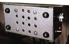
My utility amplifier was built into an aluminum Bud box and eventually ended up bolted to the bottom of a shelf as shown. The well-behaved and ready-to-go amplifier is really handy. |
As is often the case, the circuit values are not critical. Other op-amps will usually work but a bit of experience may be necessary if problems develop. The two 4.7 ohm resistors in the emitters may be replaced with a single 10 ohm resistor in either position - I just like the symmetry!
Crystal Radio (and other purpose) Audio Amplifier
Here is a simple audio amplifier using a TL431 shunt regulator. The amplifier will provide room-filling volume from an ordinary crystal radio outfitted with a long-wire antenna and good ground. The circuitry is similar in complexity to a simple one-transistor radio but the performance is superior (with the exception of the amazing one-transistor reflex ). The TL431 is available in a TO-92 package and it looks like an ordinary transistor so your hobbyist friends will be impressed by the volume you are getting with only one transistor and the amplifier may be used for other projects, too. Higher impedance headphones and speakers may also be used. An earphone from an old telephone will give ear-splitting volume and great sensitivity! The 68 ohm resistor may be increased to several hundred ohms when using high impedance earphones to save battery power.
| Here is the amplifier used to boost the output from a simple crystal radio. The volume control is at the bottom left and the other components are on the terminal strip at the bottom of the picture. This is a really quick and easy audio amplifier! | 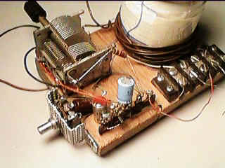 |
Class-A Audio Amplifiers
A class-A audio amplifier is pretty wasteful of power but when plenty of power is available the simplicity is attractive. Here is a simple darlington transistor example intended for use with a 5 volt power supply:
This circuit and the following aren't for beginners; they are of limited usefulness and require an understanding of the underlying principles and potential applications. They all pass DC through the speaker which is wasteful and can cause problems for the inexperienced builder. If built without variation, they should perform as described but make sure to read the text.
The 5 volts should be provided by a regulated power supply. The efficiency is below 25% and significant DC current flows in the speaker and that additional power should be figured in to the power rating of the speaker. But look how simple it is! The voltage gain is only about 20 and the input impedance is about 12k. The schematic shows two values of bias resistor to be used with the corresponding speaker impedance. With the 150k bias resistor and 8 ohm speaker, the circuit draws about 210mA (1 watt) and can deliver about 250 mW to the speaker which is plenty of volume for most small projects. The speaker should be rated at 500 mW or more and should exhibit a DC resistance near 8 ohms (perhaps 7 ohms). Check the candidate speaker with an ohmmeter; much below 7 ohms will cause excessive current draw. With the 220k resistor and 16 ohm speaker, the circuit draws about 100 mA (500 mW) and delivers about 125 mW to the speaker. The 16 ohms speaker should be rated at 200 mW or more and exhibit nearly 16 ohms of DC resistance. (Most small speakers have a DC resistance near the rated impedance and that resistance is used to set the quiescent current level in this circuit.) Other NPN darlington transistors will work but choose one that can dissipate 1 watt minimum. Most power types don't need a heatsink but tiny TO92's might overheat.
If the inefficiency of the class-A hasn't dissuaded you yet, here is a 4-transistor amplifier suitable for small signals:
The input impedance is about 5000 ohms and the frequency response is flat from 30 Hz to over 20,000 Hz. With the 8 ohm speaker the current drain is about 215 mA and the gain is about 1700 (64 dB). With the 16 ohm speaker the current gain is about 110 mA and the gain is about 2500 (68 dB). A volume control may be added by connecting one end of a 5k potentiometer to ground, the wiper to the amplifier input. The other end of the pot becomes the input.
Lets face it; just about any of the various IC audio amplifiers make more sense than this inefficient design. But, this circuit uses parts with only 3 legs. Umm, it doesn't use large capacitors except for the power supply bypassing. Lets see, its more fun-ariffic. Well, lets see if we can come up with a project that takes advantage of the inefficiency:
So, what is it?
It is a modulated light sender! Connect the input to an audio source or microphone (a speaker will work) and the audio will amplitude modulate the light intensity. The inefficiency of the class-A works in our favor now, lighting the lamp to mid-brightness with no audio present. Actually, with a 4.7 volt bulb, the lamp will be near full brightness and will be "overdriven" on sound peaks. A higher voltage bulb will last longer but will be dimmer. Try a 6.8 volt bulb as a compromise. With a sensitive detector like a phototransistor, this communicator will work several hundred feet (at night). Best range is realized if the bulb is mounted in a typical flashlight reflector and the detector is similarly mounted. The input capacitor is reduced to .01 uF to give the amplifier a high-pass character to compensate for the slow response of the bulb. The audio will sound a bit muffled, anyway. The clever designer could use this amplifier for the receiver, too, switching the speaker to the input for transmitting and to the output for listening. If you choose a detector with good infrared response, like a pin photo diode, you can add plastic IR filters to block out ambient light and make the communicator harder to see at night.
Increasing the voltage to 12 VDC, replacing the bulb with a 3 watt, 16 ohm speaker and replacing the .01uF with a 1uF gives an audio amp that will deliver nearly 1 watt of audio power. The speaker will get warm, however! (Due to the nearly 2 watts of DC power in the speaker coil.)
